CNC turning technology for deformed aluminum alloy
Due to the large plasticity, low hardness, low elastic modulus, high thermal conductivity, fast cutting heat dissipation and low melting point, deformed aluminum alloy materials have the following problems during turning: ①The friction between the workpiece and the tool generates cutting heat, and the material is easy to soften, which not only affects the surface of the part Roughness, resulting in excessive size, will also cause cutting difficulties; affect the surface quality of the workpiece. ② Due to its mechanical properties and characteristics, only turning, milling and other methods can be used to meet the requirements for surface roughness. When the surface roughness requirements are high, turning processing is more difficult. ③When the rigidity of the workpiece is poor, only a lower cutting amount can be used. Using the normal cutting amount, the parts are easy to deform, resulting in poor shape accuracy such as roundness and cylindricity. ④The hardness of the material is low, and elastic and plastic deformation are easy to occur during clamping and affect the surface and shape accuracy of the workpiece.
1. Numerical control turning content of deformed aluminum alloy
Turning the deformed aluminum alloy material on the CNC lathe, firstly comprehensively analyze the material, structure, precision, processing cost, etc. of the workpiece, and formulate the processing based on the characteristics of the process system of "machine tool → fixture → tool → workpiece". Scheme; second, determine the “clamping→support” scheme; third, select the tool (structure, material, cutting angle); fourth, determine the reasonable amount of cutting (back-feeding amount, feed rate, cutting speed); Fifth, according to the processing characteristics of CNC machine tools, rational use of relevant instructions to make up for the deficiencies of ordinary machine tools or conventional CNC technology to achieve high-quality, high-efficiency, low-cost CNC machining technology.
(1) Process plan Reasonable formulation of process plan can improve processing efficiency and ensure processing accuracy. The development of the process plan needs to be considered: on the basis of ensuring safety and quality, reducing the number of clamping and tool change, optimizing the path of the tool, reducing the route of the air knife, reasonably determining the rough and finishing contents, and selecting the appropriate cutting fluid.
(2) Fixing method The clamping method of deforming aluminum alloy workpiece in CNC lathe is fast, reliable, accurate and avoids deformation. It is the basis of CNC machining. You can use a soft claw or other method to prevent the deformation of the clip. When the installation is time-consuming, you can make a special fixture to reduce the correction time.
(3) The tool is processed on the CNC lathe, and the performance of the tool material is not high. The cutting edge of the tool is required to be sharp and the cutting is light, so as to reduce the cutting force and reduce the deformation of the workpiece; reduce the chipping phenomenon and reduce the surface. The purpose of the roughness value. High-speed steel, YG-based, YW-based hard alloy materials can meet the requirements of use. When machining a workpiece with a low surface roughness value, the machining conditions allow, and PCD materials can also be considered. In order to reduce the auxiliary time generated by the tool change, it is better to use a special aluminum alloy machine to clamp the indexable tool. Depending on the processing conditions or the structure of the workpiece, it is also possible to use a welding tool to sharpen the desired blade shape.
The rake angle of the rough car is γ o=20°?25°, and the γ o=25° 30° when finishing the car; in order to reduce the friction between the flank face of the tool and the workpiece, the main rear angle of the larger value should be taken. Select the back angle α o=8°?10°, select α o=10°?12° when finishing the car; choose λ S=0°?10° for the blade inclination angle, take the smaller value when the rough car, take the fine car Larger value. When the rigidity of the workpiece is poor, in order to reduce the cutting vibration and bending deformation, it is necessary to increase the lead angle of the tool. It can be selected at κ r=85°?93°. When finishing the car, it is best to use a straight edge repair of 0.18~0.25mm length. Light blade precision turning tool.
(4) The amount of cutting is allowed when the rigidity of the machine tool and workpiece is allowed.
It is possible to use a cutting amount that is about 3 times higher than cutting 45 steel to improve efficiency. When roughing the car, if the rigidity of the workpiece is poor, increasing the amount of back-feeding and the amount of feed will cause elastic and plastic deformation of the workpiece, which will affect the size and shape accuracy of the finished car. When using a PCD tool, use a lower backing amount, feed rate and higher cutting speed.
(5) Other problems Use programming skills and instructions to solve problems that are difficult to solve with conventional techniques.
2. Application case analysis

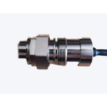
figure 1
Figure 1 is a tensile test piece processed by our center for the School of Materials and Metallurgy. The material is a deformed aluminum alloy. The mechanical properties of the material are similar to those of L F3 . Although the shape of the test piece is relatively simple, the size, shape and surface roughness of the stretched part are required to be high, the hardness and strength of the material are low, the rigidity of the workpiece is poor, and the stretched portion is only φ 3 mm, which is easily bent and deformed during turning. The cylindricity is too poor; the workpiece size is small, and the processing observation is difficult; the selection range of the geometrical angle of the cutting part of the tool is small, which is inconvenient to the tool; if the position of the tool is not suitable, the other tool will collide with the tip and the tailstock; the blank is manual Saw-cut and planed into a square material of 8m m × 8m m × 3 2mm, no clamping margin, need to adjust the head multiple times, need to make special fixtures to avoid pinching the large diameter and thread of the processed thread; When the single-action chuck is clamped, the installation is time-consuming. In summary, the test piece has poor machinability and concentrates on the processing characteristics of the deformed aluminum alloy material.
3. CNC machining content of the test piece
According to the characteristics of the deformed aluminum alloy material and the structure, blank state and precision requirements of the test piece, the processing focus of the test piece is to control the size, shape and position accuracy and surface roughness of the stretched part. The difficulty lies in avoiding the deformation of the clamping and the cutting deformation. And pinch the thread.
(1) Process plan The reasonable process plan is the basis of CNC machining. In the C K6136 CNC lathe (allowing the maximum speed n =1 600r/min), three processing plans are proposed.
Process plan A: The end of the rough car is φ 6.5mm → the diameter of one end of the finished car is φ 5.8mm → the stretched part of the semi-finished car to φ 5m m → the thread of one end is machined → the threaded end of the boring head is machined → the thread of the other end of the car The large diameter to φ 5.8mm → the stretched part of the finished car to φ 3m m → the thread.
Process plan B: One end of the rough car is φ 6.5mm → the head is clamped, the other end of the rough car is φ 6.5mm → re-clamping φ 6.5mm, the thread of one end of the finished car is φ 5.8mm → the semi-finished part of the car is bent to φ 5m m→ one end of the car thread → the head is clamped and the threaded end is machined → the other end of the car has a large diameter to φ 5.8mm → the thread is turned → the finished part is φ 3mm.
Process plan C: The end of the rough car is φ 6.5mm → the head is clamped, the other end of the rough car is φ 6.5mm → the diameter of one end of the finished car is φ 5.8mm → the stretched part of the semi-finished car to φ 5m m → the thread of one end of the car → The threaded end of the adjusting head has been machined → the thread diameter of the other end of the car is φ 5.8mm → the thread is threaded → the stretched part of the finished car is φ 3mm.
After analysis, the first solution uses only two clamping, the number of tool changes is the least, and the processing efficiency is the highest. However, the effect of the thread size and position accuracy of the machined thread is not taken into account when the diameter of the other end of the roughing machine is considered. The tension of the finished part is only φ 3 mm, the rigidity is very poor, and it is easy to machine the other end thread. The stretched portion is bent and broken.
The second solution requires four times of clamping. The third solution not only ensures the shape accuracy and processing quality of the test piece, but also has three times of clamping. This scheme is used in actual processing.
(2) Selection of tool roughing tool: The size of the test piece is small and requires top support, which limits the structure of the cutter head. Therefore, the rough turning tool is sharpened by Y G8 welding type thread turning tool. The leading angle κ r=60°, the secondary declination κ r'=60°, the rake angle γ o=25°, the relief angle α o =8°, λ S=5°, which ensures the strength of the cutting part of the tool while maintaining the sharpness of the tool and reducing the radial cutting force.
Semi-finishing turning tool: It is made of high-speed steel material and sharpened by welding type turning tool. The leading angle of the cutting head is κr=85°?93°, the auxiliary declination κr'=45°, the rake angle γ o=30°, after The angle α o=10°, λ S=10°, mainly considers the sharpness of the cutting edge, the cutting light is light, the radial cutting force is reduced, and the interference of the tool vice knives facing the right end arc is avoided.
Fine turning tools: High-speed steel, Y W1, Y G3, Y G6 and other materials can be used, and diamond tools can be used under the conditions. According to the material and structure of the test piece, the welded high-speed steel spring cutter is used to sharpen the arc knife into a circular arc. The radius of the cutter head is R = 2m m, the rake angle γ o = 0°, and the relief angle α o = 10°. Reduce the friction of the secondary knives facing the machined surface and improve the surface accuracy. The secondary declination angle α o'=15°, λ S=5°.
In the case of fully casting the cutting fluid, when the smaller feed rate is selected, the machined surface is stabilized to reach Ra = 0.4 to 0.8 μm.
Threading knives: Welded thread turning tools are used, the material is YG8.
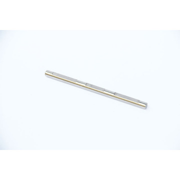
(3) The clamping method According to the shape of the blank of the test piece, the self-centering chuck + special fixture 1 (see Fig. 2a) is used for the first roughing, which solves the problem of time-consuming and clamping deformation of the blank clamping. When the head is roughed, the self-centering chuck + special fixture 2 (see Figure 2b) is used for clamping, which solves the problem of the coaxiality accuracy requirement of the test piece and the large diameter of the broken thread; when the other end of the thread is used, the self-determination is adopted. The heart chuck + special fixture 3 (see Figure 2c) is clamped to avoid pinching the thread and meeting the coaxiality accuracy requirements.

figure 2
(4) Cutting amount According to the material of the part and the structure and size of the test piece, the roughing speed n =1 600r/min, the feeding amount f=0.2mm/r; the semi-finishing speed n =1 600r/min, the feeding amount f=0.10mm/r, the amount of back-feeding knife is successively decreased; the speed of finishing vehicle n is =1 600r/min, and the feed rate is f=0.03mm/r.
(5) The existence of the cutting fluid shield provides a reliable guarantee for the full use of cutting fluid on CNC machine tools. The correct use of cutting fluid, in the processing of aluminum alloy materials, is conducive to chip breaking, and can avoid the softening of the material to form built-up edge, reduce the thermal elongation of the parts, and significantly reduce the surface roughness of the parts. According to the principle that the market is easy to purchase, the cost is low, and the processing quality is guaranteed, the special cutting fluid for aluminum alloy can be used, which can avoid the corrosion of the surface of the parts by using the extreme pressure emulsified cutting fluid during finishing. Its composition is made up of extreme pressure lubricants, rust inhibitors, surfactants, etc. It is a new generation of environmentally-friendly and high-quality water-soluble cutting fluid specially developed for aluminum and aluminum alloy processing. The aluminum alloy cutting fluid provides excellent lubricity and cooling required for high-speed cutting during aluminum machining, significantly improving tool life and reducing surface roughness. Even in the face of high-precision deep hole machining applications, the machining requirements can be met.
4. CNC turning process
Three setups require three programs to be programmed manually:
The first procedure, drilling the center hole, the active top support. Use a rough turning tool twice to rough up to φ 6.5mm; end the first procedure.
The second procedure, after all the specimens are roughed at one end, clamps the φ 6.5mm end, drills the center hole, and moves the top support. The other end of the roughing car is φ 6.5mm, and the semi-finishing turning tool is used for one-step continuous chamfering, the thread diameter is φ 5.8mm, the tensioning part is φ 5m m; the threaded turning tool is threaded at one end, and “MOO” is used. "Pause command to check if the thread is qualified."
The third procedure: the threaded large diameter of the clamped processing, the active top support. Change the semi-finished turning tool for one-pass continuous chamfering and thread large diameter φ 5.8mm; change the thread of the other end of the threaded turning tool, use the “MOO” pause command to check whether the thread is qualified; then change the semi-fine turning tool twice The car transitions to the arc, and the car is stretched twice to φ 3.2mm; the car is changed, the transition arc of the tool is moved once, and the stretched part is required to the size of the pattern. Use the "MOO" pause command to check if φ 3mm is acceptable.
5. Precautions
All the three clamps are made of aluminum alloy. In order to ensure the coaxiality between the outer circle and the inner hole of each clamp, the one-time clamping is completed in the lathe, and the CNC cutting machine is used to ensure the symmetry from the middle of the fixture. Points, and leave a gap of 1m m. After roughing, you can use soft claws or trim chuck jaws to ensure the coaxiality of the test piece.
Through the actual CNC turning, it is proved that the above method is feasible when turning the rust-proof aluminum alloy workpiece on the CNC lathe. The size, shape and position accuracy and surface roughness of the processed test piece completely meet the requirements of the pattern, and the efficiency is obviously improved. Solved the problems that often occur when turning anti-rust aluminum alloy materials.


 September 29, 2020